As a laptop technician, you know that motherboard repairs can be one of the most challenging tasks, especially when dealing with chip-level issues. The Lenovo IdeaPad G505 is a reliable machine, but like any other laptop, its motherboard can develop problems over time. Fortunately, with the right tools and resources, you can diagnose and fix these issues efficiently. One such invaluable resource is the LA-9911P R1.0 Schematic Diagram. In this blog post, we’ll walk you through how to troubleshoot and fix common chip-level issues on the Lenovo IdeaPad G505 motherboard using this schematic diagram.
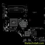
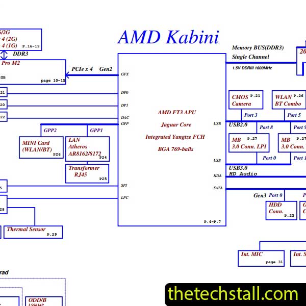
The LA-9911P R1.0 Schematic Diagram is a detailed blueprint of the Lenovo IdeaPad G505 motherboard. It provides a comprehensive view of the circuitry, component placements, and signal flow, making it an indispensable tool for chip-level repairs. Without this diagram, diagnosing issues like power failures, short circuits, or faulty components can feel like navigating a maze blindfolded.
By using the LA-9911P R1.0 Schematic Diagram, you can:
Before diving into the troubleshooting process, let’s look at some common chip-level issues you might encounter with the Lenovo IdeaPad G505 motherboard:
These issues often stem from problems like damaged capacitors, faulty MOSFETs, or broken traces on the motherboard. With the LA-9911P R1.0 Schematic Diagram, you can pinpoint the exact cause and fix it effectively.
Before starting, ensure you have the following tools:
Start by visually inspecting the motherboard for obvious signs of damage, such as:
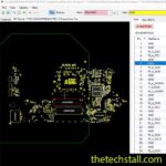
Use the LA-9911P R1.0 Schematic Diagram to locate these components and verify their condition.
A short circuit is a common cause of no-power issues. To check for shorts:
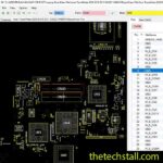
Using the schematic diagram, identify key test points on the motherboard. Measure the voltage and resistance at these points to ensure they match the values specified in the diagram. For example:
If the readings are off, the corresponding component may need replacement.
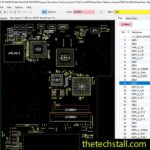
Once you’ve identified the faulty component, carefully desolder it and replace it with a new one. Use the LA-9911P R1.0 Schematic Diagram to ensure proper placement and orientation.
After completing the repairs, reassemble the laptop and test it. Check for:
To make your repair process even easier, we’re offering a free download link for the LA-9911P R1.0 Schematic Diagram. This diagram will serve as your go-to guide for troubleshooting and fixing chip-level issues on the Lenovo IdeaPad G505 motherboard.
Download “Lenovo IdeaPad G505 LA-9911P R1.0 Schematic Diagram” view – Downloaded 472 times – 33.07 KBChip-level motherboard repairs can be daunting, but with the right tools and resources, they become manageable. The LA-9911P R1.0 Schematic Diagram is a game-changer for laptop technicians, providing the clarity and precision needed to diagnose and fix complex issues.

For tips on chip-level repair of laptop and desktop motherboards, visit our YouTube channel Repair Assistant and subscribe to our Facebook page repairassiastantbd for repair resource updates.
You also may be interested in
If you found this guide helpful, share it with fellow technicians and leave a comment below with your thoughts or questions. Happy repairing!