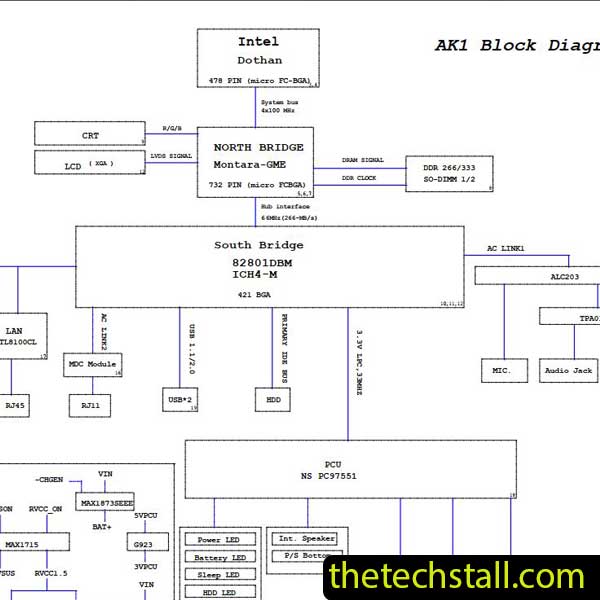
A schematic diagram is a drawing that shows the connections of all the parts used in a circuit. Learn more about schematics.
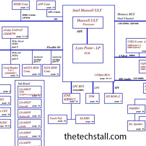
Here you can free download Acer Aspire R7-572_572G LA-A021P Rev 1.0 schematic diagram and all the materials and information needed to repair a laptop motherboard are available on our site.
Laptops need to be repaired to reduce waste and make them reusable. Repairing laptop motherboard without schematic diagram is very difficult and time consuming. This is our effort to help you repair laptop motherboard easily and in less time.
Apart from this laptop schematic diagram, you are looking for other laptop motherboard schematic diagram, if it is not in our site, let us know by comment. We will try to upload and notify you as soon as possible.
How to Read a Schematic Diagram: Understanding the Basics
If you’re new to electronics, the sight of a schematic diagram can be intimidating. With its jumble of symbols and lines, it can look like a foreign language. But fear not, for once you learn to read a schematic, you’ll have a powerful tool to help you understand and design circuits. In this article, we’ll cover the basics of how to read a schematic diagram.
Understanding Symbols
One of the key elements of a schematic diagram is the use of symbols to represent the different components of a circuit. Each symbol represents a different component, such as a resistor, capacitor, or transistor. Understanding what these symbols mean is crucial to being able to read a schematic.
Common Symbols
Here are some of the most common symbols you’ll see on a schematic diagram:
- Resistor: represented by a zigzag line
- Capacitor: represented by two parallel lines
- Diode: represented by an arrow pointing from the anode (positive) to the cathode (negative)
- Transistor: represented by a set of three lines, with the middle line being longer than the others
- Battery: represented by a set of long and short lines, with the long line representing the positive terminal
- Ground: represented by a line with three horizontal bars
Reading Component Values
In addition to the symbols, schematics often include values for each component. These values are typically written next to or inside the symbol and indicate important information about the component, such as its resistance, capacitance, or voltage rating.
Tracing Connections
Once you understand the symbols and values, the next step is to trace the connections between the components. This involves following the lines on the schematic to see how the different components are connected together. It’s important to pay attention to the direction of the lines and the order in which the components are connected.
Conclusion
Reading a schematic diagram may seem daunting at first, but with a little practice, it becomes a valuable skill for anyone interested in electronics. By understanding the symbols, values, and connections in a schematic, you can gain insight into how a circuit works and even design your own circuits.
Download without any registration
If there is a problem with the laptop bios bin, schematic and boardview files downloaded from our website, please contact the tech stall support team. Tech stall team will try their best to solve your problem within 24 hours.