For laptop motherboard technicians, having the correct schematic diagram is often the difference between guessing and performing a precise chip-level repair. If you work on laptops, especially the Lenovo Yoga 370, the LA-E291P schematic diagram is one of the most valuable technical resources you can have in your toolkit.
This guide explains how the LA-E291P schematic diagram helps diagnose motherboard faults, which repair resources work best alongside it, and how technicians can use it to solve chip-level errors quickly and professionally.
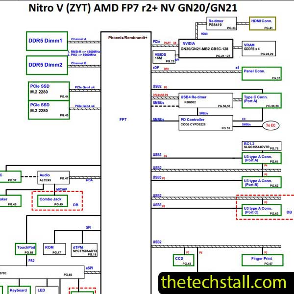
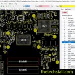
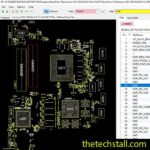
The LA-E291P schematic diagram is a detailed electronic blueprint of the Lenovo Yoga 370 motherboard. It shows the complete electrical design of the board, including:
Unlike simple board layouts, schematic diagrams show how the circuits actually work, which allows technicians to trace faults at the chip level.
With the LA-E291P schematic diagram, you can follow the entire power sequence and identify exactly where the problem originates.
Many technicians attempt motherboard repair using trial-and-error methods. While that sometimes works, it wastes time and risks damaging components.
The LA-E291P schematic diagram allows technicians to work like professionals by providing:
Power problems are among the most common motherboard failures. The schematic shows all voltage lines such as:
By checking these rails with a multimeter, technicians can quickly isolate faulty regulators or MOSFETs.
Motherboards contain hundreds of tiny components. The schematic diagram labels each component with identifiers like:
This makes locating faulty components much easier during repair.
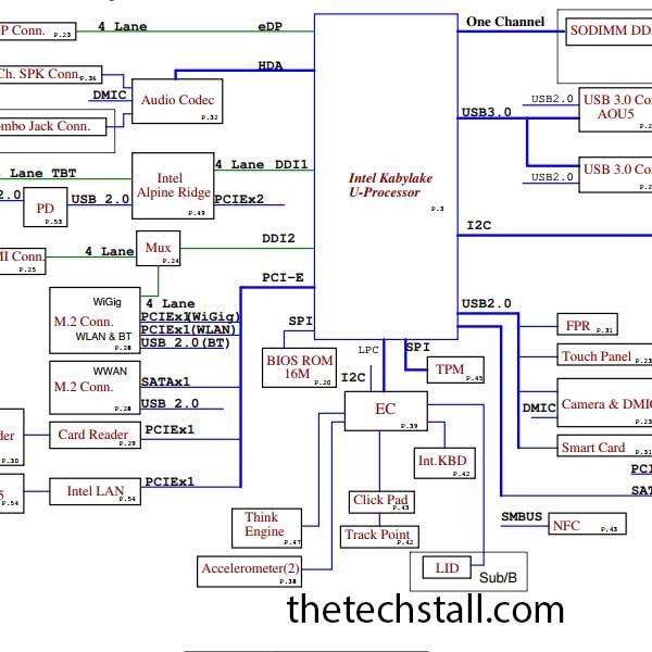
When troubleshooting problems like no display or no POST, the LA-E291P schematic diagram helps technicians trace signals between:
Understanding this communication flow is critical for diagnosing deeper motherboard faults.
Using the LA-E291P schematic diagram, technicians can troubleshoot many common issues found in the Lenovo Yoga 370 motherboard.
Possible causes include:
The schematic helps locate the power management circuit responsible for startup.
In this case, technicians should inspect:
The LA-E291P schematic diagram helps trace these signals step-by-step.
Charging circuit faults often occur due to:
Using the schematic allows technicians to test each component logically.
Professional technicians rarely rely on just one file. The LA-E291P schematic diagram works best when used with additional repair resources.
Boardview software maps the physical location of components on the motherboard.
Popular tools include:
When combined with the LA-E291P schematic diagram, technicians can instantly locate components on the board.
Power sequence diagrams show the exact startup order of voltages. These help identify why a laptop fails during boot.
Technicians often compare the power sequence with the LA-E291P schematic diagram to locate where the startup process stops.
Hardware tools are essential for verifying signals shown in the schematic.
Technicians typically use:
These tools help confirm voltage levels and signal activity shown in the LA-E291P schematic diagram.
Sometimes motherboard issues come from corrupted firmware. Repair technicians may use:
This works alongside the schematic when troubleshooting boot failures.
To maximize the value of the LA-E291P schematic diagram, technicians should follow these professional practices:
✔ Start troubleshooting from power rails
✔ Check for short circuits first
✔ Verify standby voltages before pressing power
✔ Follow the power-on sequence in order
✔ Use boardview software for component location
These steps help reduce repair time and improve success rates.
Technicians who want to repair the Lenovo Yoga 370 motherboard can download the schematic using the link below.
Download “Lenovo Yoga 370 Compal LA-E291P Rev 0.3 Schematic” Lenovo-Yoga-370-Compal-LA-E291P-Rev-0.3-Schematic.zip – Downloaded 448 times – 3.90 MBFor technicians specializing in laptop motherboard chip-level repair, the LA-E291P schematic diagram is an essential diagnostic tool. It provides a clear understanding of the Lenovo Yoga 370 motherboard design and helps identify faults accurately.
When combined with boardview files, power sequence charts, BIOS dumps, and proper testing tools, this schematic can dramatically improve repair efficiency and accuracy.
Instead of guessing the problem, technicians can follow the electrical design and solve issues like professionals.

For tips on chip-level repair of laptop and desktop motherboards, visit our YouTube channel Repair Assistant and subscribe to our Facebook page repairassiastantbd for repair resource updates.