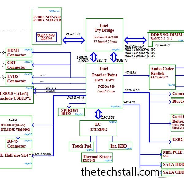
Laptop motherboards are complex electronic circuits that power and control various components within a laptop. When these motherboards encounter issues, repairing them can be a daunting task without proper guidance and documentation. This is where Lenovo IdeaPad Z500-P500 LA-9061p Rev 2.A schematic diagrams come into play.
While the Lenovo IdeaPad Z500-P500 LA-9061p Rev 2.A Schematic Diagram is a valuable resource for laptop motherboard repairs, a boardview file offers additional advantages. The detailed physical component placement, trace information, identification of test points, compatibility with repair software, and collaborative potential make the boardview file a valuable tool in the repair process. By utilizing both the schematic diagram and the boardview file, technicians can enhance their diagnostic capabilities, streamline repairs, and ensure the successful restoration of laptop motherboards to optimal working condition.
Lenovo Laptop Motherboard BoardView File Collection
A Lenovo IdeaPad Z500-P500 LA-9061p Rev 2.A Schematic Diagram is a graphical representation of the laptop motherboard’s electrical circuitry. It provides detailed information about the various components, their interconnections, and the flow of signals within the circuit. This diagram serves as a blueprint that helps technicians diagnose and fix issues with the motherboard effectively.
Laptop motherboards are intricate assemblies of numerous electronic components, such as resistors, capacitors, transistors, and integrated circuits. When a motherboard malfunctions, it can be challenging to identify the specific faulty component without proper guidance. Schematic diagrams act as a roadmap, guiding technicians through the complex circuitry and enabling them to identify and rectify the root cause of the problem.
A schematic diagram is a graphical representation of an electrical circuit. It uses symbols and lines to represent different components and their connections. The primary purpose of a schematic diagram is to provide a visual representation of the circuit, aiding in understanding its functionality and enabling effective troubleshooting and repairs.
Here are some common components and symbols you may come across in a Lenovo IdeaPad Z500-P500 LA-9061p Rev 2.A Schematic Diagram:
These are just a few examples of the components and symbols used in schematic diagrams. The Lenovo IdeaPad Z500-P500 LA-9061p Rev 2.A Schematic Diagram will include specific symbols related to the components present in the laptop’s motherboard.
Before you can use a schematic diagram to repair a faulty laptop motherboard, you need to obtain the schematic diagram. You can obtain the schematic diagram from the manufacturer of the laptop or from third-party sources online. It is important to obtain the correct schematic diagram for your laptop model. We hope to get the correct Schematic Diagram of Lenovo IdeaPad Z500-P500 LA-9061p Rev 2.A from us.
Lenovo IdeaPad Z500-P500 LA-9061p Rev 2.A Laptop Motherboard Schematic Diagram can be downloaded for free from the link below, without any registration. Lenovo IdeaPad Z500-P500 Laptop Motherboard Schematic Diagram in PDF format. This diagram can be opened using any PDF reader software such as FOXIT PDF Reader or Adobe Acrobat Reader.
When it comes to laptop motherboard repairs, two important resources that technicians rely on are schematic diagrams and boardview files. Both these tools provide valuable insights into the circuitry and components of a motherboard, but they serve different purposes. In this article, we will explore the difference between schematic diagrams and boardview files, understanding their unique functionalities and how they contribute to the repair process.
A schematic diagram, as mentioned earlier, is a visual representation of an electrical circuit or system. It uses standardized symbols to represent various electronic components and their connections. Schematic diagrams provide an overview of the circuitry, allowing technicians to understand the flow of signals and identify key components. Here are some key characteristics of schematic diagrams:
While schematic diagrams provide an overview of the circuitry, boardview files offer a more detailed view of the physical layout of the motherboard. A boardview file is essentially a 2D representation of the motherboard’s layers, with detailed information about component placement and traces. Here are the key characteristics of boardview files:
In summary, schematic diagrams and boardview files are essential tools in laptop motherboard repairs. While schematic diagrams provide a high-level view of the circuitry and aid in troubleshooting, boardview files offer detailed information about the physical layout and assist in component placement. Both these resources complement each other, allowing technicians to diagnose and repair complex electronic systems effectively.
Share with friends
thetechstall.com would like to share with you all the resources you need to repair desktop and laptop motherboards for free.
Developed By: Ibrahim Hossen