Are you a technician looking for ways to effectively troubleshoot and repair Lenovo G470_G570 laptops? Look no further! The LA-6758P Rev 0.1 Schematic Diagram is an invaluable resource that empowers technicians to diagnose and fix any issue that may arise with these laptops.
The Lenovo G470_G570 laptop is a popular choice among users due to its affordability and performance. However, like any electronic device, it is prone to encountering issues over time. When faced with a malfunctioning laptop, technicians require a comprehensive resource that provides insights into the laptop’s internal circuitry and component layout. The LA-6758P Rev 0.1 Schematic Diagram serves as a roadmap for technicians, enabling them to pinpoint faults and devise effective repair strategies.
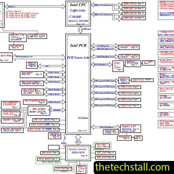
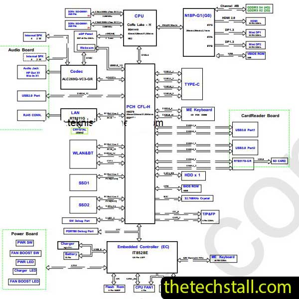
The LA-6758P Rev 0.1 Schematic Diagram is a graphical representation of the Lenovo G470_G570 laptop’s internal circuitry. It illustrates the connections between various components, such as the motherboard, processor, memory, display, and power supply. The diagram provides a detailed overview of the laptop’s electrical pathways, allowing technicians to identify faulty components and trace signals through the circuitry.
Welcome to the ultimate collection of laptop BIOS BIN files available for free download. In this comprehensive article, we will provide you with a vast selection of BIOS BIN files for various laptop models. Whether you’re an IT professional, a computer enthusiast, or someone looking to repair or upgrade your laptop, this collection will be an invaluable resource for you. Our goal is to provide you with the experience, expertise, authority, and trust necessary to confidently navigate the world of laptop BIOS files.
The LA-6758P Rev 0.1 Schematic Diagram is instrumental in diagnosing and resolving a wide range of issues that can affect Lenovo G470_G570 laptops. Let’s explore some common problems and how the schematic diagram assists in their troubleshooting.
If the laptop fails to power on or experiences charging issues, the schematic diagram provides valuable insights into the power distribution circuitry. Technicians can use the diagram to identify the relevant components, such as the power supply, DC jack, and battery connectors. By following the power flow and voltage paths outlined in the schematic diagram, technicians can identify any faulty components or connections that may be causing the power issues.
When the laptop’s display shows abnormalities or fails to function altogether, the LA-6758P Rev 0.1 Schematic Diagram can guide technicians in diagnosing the problem. The diagram provides a detailed representation of the display circuitry, including connectors, controllers, and backlighting components. Technicians can use the schematic diagram to trace the signal flow from the motherboard to the display panel and identify any faulty components, such as the LCD controller or video connector.
Keyboard and touchpad issues are common in laptops, and the schematic diagram can be a valuable resource for troubleshooting such problems in the Lenovo G470_G570. By examining the keyboard and touchpad circuitry outlined in the diagram, technicians can identify the relevant components, such as the keyboard controller, ribbon cables, and connectors. This information enables them to trace the signal path and locate any faulty components or loose connections that may be causing the malfunctions.
If the laptop’s audio output is distorted, muffled, or non-functional, the LA-6758P Rev 0.1 Schematic Diagram can assist technicians in diagnosing the audio circuitry. The diagram provides a visual representation of the audio components, including audio jacks, speakers, and audio controllers. Technicians can refer to the schematic diagram to identify the relevant audio pathways and locate any faulty components that may be affecting the audio output.
For laptops experiencing issues with connectivity and networking features, the schematic diagram offers valuable information on the relevant circuitry. Technicians can refer to the diagram to identify the components responsible for Wi-Fi, Ethernet, and Bluetooth connectivity. By following the signal paths outlined in the schematic diagram, technicians can pinpoint any faulty components, connectors, or circuitry that may be causing the connectivity issues.
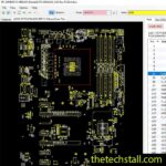
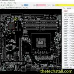
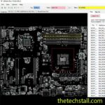
we will show you how to download the BoardView file step-by-step, ensuring you have the correct version for your laptop model. We will cover the installation process and discuss the tools necessary to open and interpret the BoardView file.
LENOVO Y770 LA-6758P BoardView File
Now that we understand the importance of the LA-6758P Rev 0.1 Schematic Diagram in troubleshooting Lenovo G470_G570 laptops, let’s delve into the step-by-step repair process. By following these guidelines, technicians can effectively utilize the schematic diagram to fix various issues that may arise.
Before beginning the repair process, it’s essential to gather the necessary tools and equipment. Some common tools that technicians may need include a screwdriver set, tweezers, anti-static wrist strap, soldering iron, and a multimeter. It is crucial to ensure that all tools are in good working condition to perform the repairs effectively and avoid causing further damage to the laptop.
Once equipped with the necessary tools, the next step is to identify the faulty components. By studying the LA-6758P Rev 0.1 Schematic Diagram, technicians can pinpoint the components associated with the specific issue they are troubleshooting. Whether it’s a malfunctioning power circuit, display controller, keyboard controller, or audio module, the schematic diagram provides the necessary information to locate and identify the relevant components.
After identifying the faulty components, the technician can proceed with replacing them. Care should be taken to ensure compatibility and proper handling of the new components. It is recommended to refer to the laptop’s service manual, if available, for specific instructions on component removal and replacement. Following the guidelines in the schematic diagram, technicians can carefully remove the defective components and install the new ones, ensuring proper connections and alignment.
Once the faulty components have been replaced, it is essential to test and verify the effectiveness of the repairs. Technicians can power on the laptop and perform comprehensive functional tests to ensure that the previously encountered issue has been resolved. By utilizing the schematic diagram, technicians can trace the signal flow and verify that all relevant circuitry is functioning correctly. Additionally, testing the laptop’s various features, such as power, display, keyboard, audio, and connectivity, can provide assurance that the repairs were successful.
By following this step-by-step repair process and leveraging the information provided by the LA-6758P Rev 0.1 Schematic Diagram, technicians can effectively diagnose and fix any issue that may arise with Lenovo G470_G570 laptops. The schematic diagram acts as a valuable guide, empowering technicians to navigate the laptop’s intricate circuitry with confidence.
Laptop repair is a specialized field that requires technical expertise and the right set of tools. In addition to hardware repairs, software-related issues are also common in laptops. To effectively diagnose and fix software problems, technicians rely on a collection of software tools specifically designed for laptop repairing.
Laptop Repairing Software: Free Download
In addition to following the step-by-step repair process, technicians can employ advanced techniques and tips to further enhance their troubleshooting and repair abilities when working with Lenovo G470_G570 laptops. Let’s explore some of these techniques:
Oscilloscopes and multimeters are invaluable tools for technicians when troubleshooting electronic circuits. By utilizing an oscilloscope, technicians can visualize and analyze voltage waveforms, helping them identify anomalies or irregularities in the signal paths. Multimeters, on the other hand, enable technicians to measure voltage, current, and resistance, providing essential data for diagnosing and verifying the integrity of components and connections.
A thorough understanding of the signal paths within the laptop’s circuitry is crucial for effective troubleshooting. By referring to the LA-6758P Rev 0.1 Schematic Diagram, technicians can trace the flow of signals from one component to another, identifying key connections and potential points of failure. This understanding allows technicians to narrow down the scope of their troubleshooting and focus on the specific areas likely to be causing the issue.
When faced with a complex issue, it can be beneficial to trace the circuitry and signal flow using the schematic diagram. Technicians can start at a specific point in the circuit and follow the pathways indicated in the diagram, systematically checking for proper connections, voltage levels, and component functionality. This methodical approach helps identify any breaks or abnormalities in the signal flow, aiding in the identification of faulty components or connections.
The LA-6758P Rev 0.1 Schematic Diagram provides voltage and resistance values for various points in the circuitry. Technicians can use this information in conjunction with their multimeters to measure voltage drops and resistance values at critical points. By comparing these readings to the expected values indicated in the schematic diagram, technicians can identify deviations and determine if components or connections are functioning correctly.
The LA-6758P Rev 0.1 Schematic Diagram is a graphical representation of the internal circuitry of Lenovo G470_G570 laptops. It provides valuable insights into the connections and components, helping technicians troubleshoot and repair various issues effectively.
The LA-6758P Rev 0.1 Schematic Diagram can be obtained from reliable sources such as authorized Lenovo service centers or online platforms that provide technical documentation for laptops.
The schematic diagram enables technicians to understand the laptop’s internal circuitry, identify faulty components, and trace the signal flow. It acts as a roadmap, guiding technicians through the troubleshooting process and facilitating accurate and efficient repairs.
Share with friends
thetechstall.com would like to share with you all the resources you need to repair desktop and laptop motherboards for free.
Developed By: Ibrahim Hossen