In the high-stakes world of chip-level laptop repair, precision isn’t just a goal—it’s a requirement. If you’ve ever stared down a Dell E5530 that refuses to power on, you know that the difference between a successful fix and a “no-fix” often comes down to the quality of your documentation.
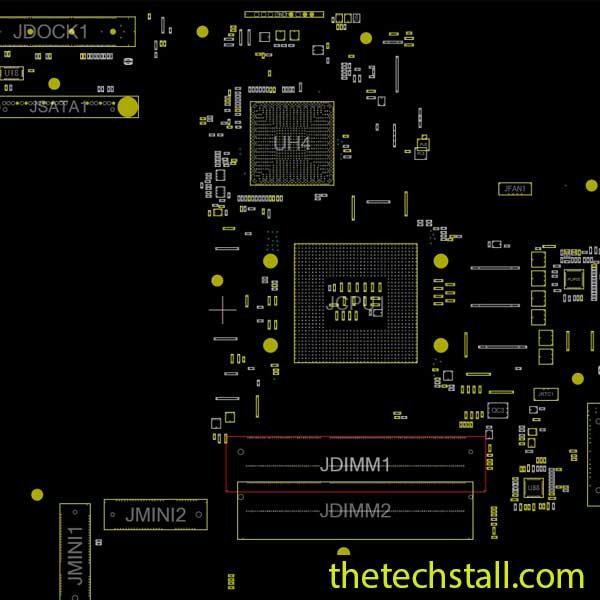
For professional technicians, the QXW10 LA-7902P BoardView File is the ultimate roadmap. While a schematic tells you how a circuit works, the BoardView tells you exactly where that circuit lives on the physical PCB. Today, we’re diving deep into how to leverage this file to revive one of Dell’s most enduring workhorses.
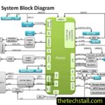
The QXW10 LA-7902P is a complex, multi-layered motherboard. When dealing with “No Power,” “No Display,” or “Short to Ground” issues, visual inspection rarely suffices. Components are packed tightly, and tracing a 19V rail or a low-voltage signal like PLT_RST# by eye is impossible.
The QXW10 LA-7902P BoardView File allows you to:
The journey begins at the DC jack. Using your BoardView software (like OpenBoardView or NeoViewer), search for the entry point of the +19V_VIN.
The Dell E5530 won’t show a sign of life without the standby voltages.
If your primary rails are healthy but the laptop won’t trigger, it’s time to check the SIO (Super I/O) chip.
PWR_SW# or RSMRST# manually is a nightmare. By clicking the signal name in the BoardView, the software will highlight the exact pin and every connected component. This is where you verify if the power button signal is actually reaching the controller.While the QXW10 LA-7902P BoardView File is powerful, combining it with other tools enhances your efficiency:
A schematic diagram provides circuit logic and signal flow, complementing the visual layout of the BoardView file.
Essential for measuring voltage, resistance, and detecting shorts.
Useful for analyzing clock signals and data communication in advanced repairs.
Required for reprogramming corrupted BIOS chips.
Helps detect overheating or shorted components quickly.
Using these tools together with the QXW10 LA-7902P BoardView File allows technicians to perform professional-level diagnostics with confidence.

For tips on chip-level repair of laptop and desktop motherboards, visit our YouTube channel Repair Assistant and subscribe to our Facebook page repairassiastantbd for repair resource updates.
When working on the QXW10 LA-7902P, always pay attention to the RTC (Real-Time Clock) circuit. A depleted CMOS battery or a corroded RTC resistor (easily found via BoardView near the coin cell connector) can cause these boards to loop or fail to POST.
Additionally, the Dell E5530 is prone to liquid damage near the touchpad area, which sits directly over critical power circuitry. Use the BoardView to check for “via” continuity—the tiny holes that pass signals between board layers—as these are the first to rot away from corrosion.
Ready to get started on your Dell E5530 repair? We’ve got you covered. Click the link below to access our repository and get your copy of the boardview File.
If you’re serious about improving your chip-level repair skills, working alone will slow you down. That’s why joining a dedicated repair network makes a real difference.
Our community at:
👉 https://repaircommunity.thetechstall.com/
Gives you access to:
Instead of wasting hours searching for a single repair resource file in different places, join our repair community for free and request the file you want. Our tech support team will try to deliver it as quickly as possible. This is an effective way to improve quickly.
Investing time into mastering the QXW10 LA-7902P BoardView File separates the “parts changers” from the “chip-level experts.” It reduces diagnostic time from hours to minutes and increases your shop’s success rate, which directly impacts your bottom line.
Whether you are dealing with a simple shorted capacitor or a complex logic failure between the SIO and PCH, this file is your most trusted ally on the workbench.