In the world of laptop and desktop motherboard repair, experience matters — but even the most skilled technician can lose valuable time without the right technical documents. When it comes to repairing the Acer Veriton M4640G motherboard, one resource stands out above the rest: the 14065-1 Schematic Diagram.
For chip-level technicians, this schematic is more than just a wiring reference. It’s a roadmap that helps identify faults faster, trace power rails accurately, and repair dead boards with confidence. Whether you’re dealing with no power, no display, short circuits, or unstable voltage lines, having access to the correct schematic can completely change the repair process.
Every motherboard is built with hundreds of tiny components connected through complex circuits. Without a schematic, troubleshooting often becomes guesswork. You might spend hours checking random components or replacing ICs that were never faulty in the first place.
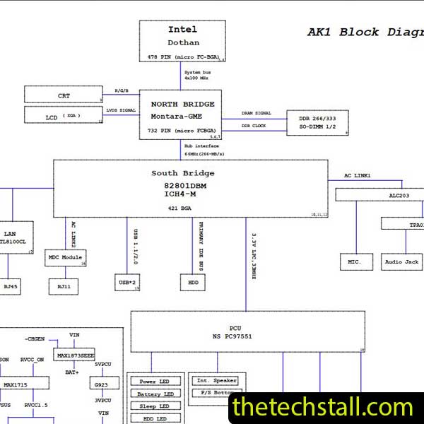
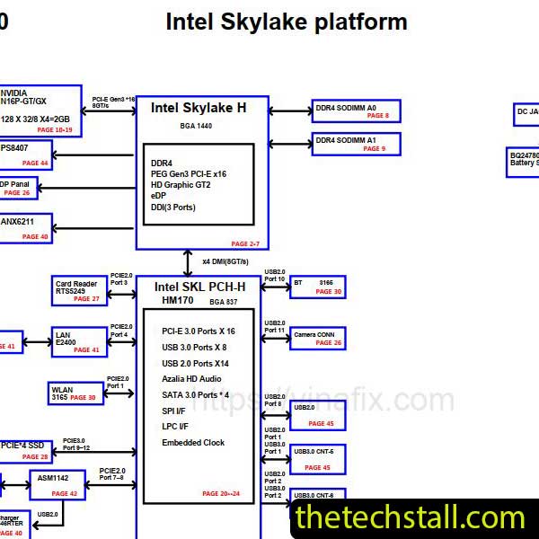
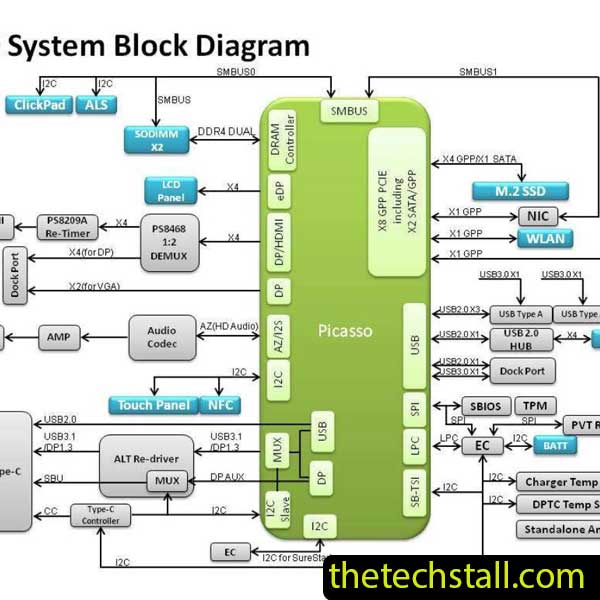
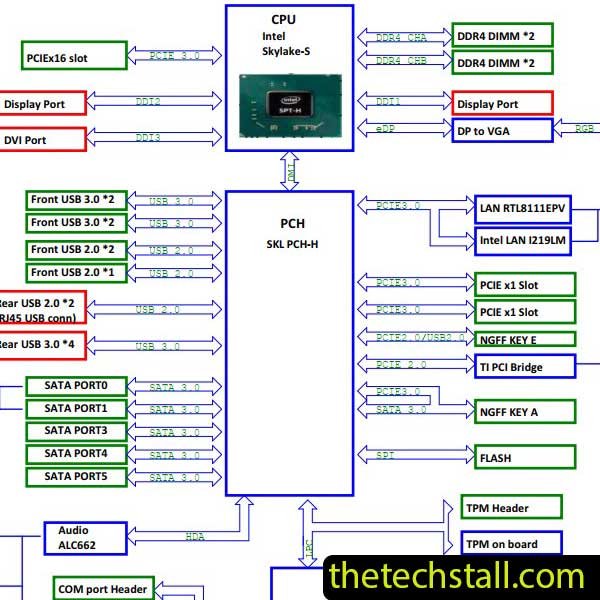
The 14065-1 Schematic Diagram gives technicians a clear understanding of how the Acer Veriton M4640G motherboard is designed. It shows detailed circuit paths, voltage lines, component references, charging sections, BIOS circuits, CPU power sequences, and signal flow between important chips.
That matters because modern motherboards are no longer simple boards. A single missing voltage can prevent the entire system from powering on. With the schematic in hand, technicians can quickly locate the source of the issue instead of wasting time on blind testing.
Anyone working in a repair shop knows how important turnaround time is. Customers expect quick service, and delays can hurt both reputation and profit.
Using the 14065-1 Schematic Diagram, technicians can narrow down faults much faster. For example:
Instead of relying only on experience or trial-and-error methods, the schematic provides a structured repair path. That alone can save hours on difficult repairs.
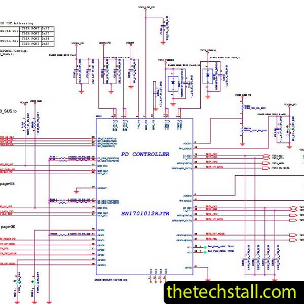
One of the biggest challenges in chip-level repair is signal tracing. A technician may detect missing voltage on a coil but still struggle to understand where the line originates or which IC controls it.
This is where the 14065-1 Schematic Diagram becomes incredibly useful.
It allows technicians to:
Honestly, without a schematic, even simple repairs can become frustrating. But once you understand the circuit flow, the board starts “speaking” to you in a way that makes troubleshooting much more logical.
Most experienced technicians don’t rely on schematics alone. They combine them with BoardView files for precise component identification.
While the 14065-1 Schematic Diagram explains the electrical design, a BoardView file helps locate components physically on the motherboard. Using both together creates a much smoother workflow.
For example:
That combination reduces mistakes and speeds up component replacement, especially when working with densely packed multilayer motherboards.
Professional technicians often build a repair toolkit that goes beyond a single schematic file. To get the best results from the 14065-1 Schematic Diagram, it’s smart to use additional repair resources alongside it.
Some of the most useful include:
These help identify exact component positions and make board-level navigation easier during repairs.
Corrupted BIOS firmware is a common issue in modern systems. Having clean BIOS dumps can help restore dead or unstable motherboards.
These charts simplify startup diagnostics by showing which voltages should appear during each power stage.
For advanced technicians, waveform analysis can reveal clock or signal problems that are difficult to detect with a multimeter alone.
Datasheets for PWM controllers, MOSFETs, charging ICs, and embedded controllers provide deeper insight into circuit behavior.
When all these resources are used together, repair accuracy improves dramatically.

For tips on chip-level repair of laptop and desktop motherboards, visit our YouTube channel Repair Assistant and subscribe to our Facebook page repairassiastantbd for repair resource updates.
If you repair Acer Veriton M4640G motherboards regularly, keeping the 14065-1 Schematic Diagram in your repair library is a smart move. It can save time, improve repair accuracy, and make complex troubleshooting much easier.
The 14065-1 Schematic Diagram is not only helpful for professionals. It’s also an excellent learning resource for new technicians entering the chip-level repair industry.
Studying real motherboard schematics teaches important concepts like:
Many successful technicians improved their diagnostic skills simply by practicing with schematics every day. Over time, reading circuit diagrams becomes second nature.
If you’re serious about improving your chip-level repair skills, working alone will slow you down. That’s why joining a dedicated repair network makes a real difference.
Our community at:
https://repaircommunity.thetechstall.com/
Gives you access to:
Instead of wasting hours searching for a single repair resource file in different places, join our repair community for free and request the file you want. Our tech support team will try to deliver it as quickly as possible. This is an effective way to improve quickly.