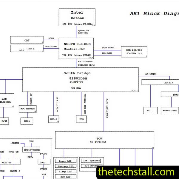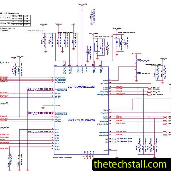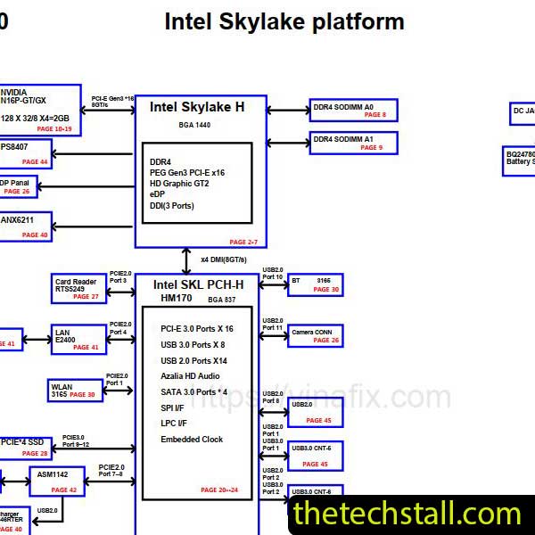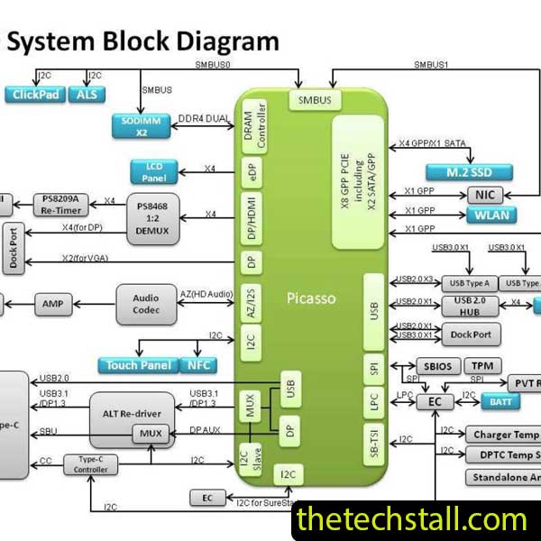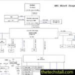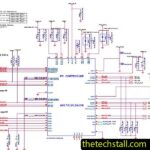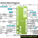

If you are repairing a Toshiba L740 laptop motherboard at chip level, having the correct circuit documentation can save a surprising amount of time. The DA0TE4MB6D0 Schematic Diagram gives technicians a practical view of the board’s power circuits, component connections, signal paths, and major circuit sections.
When a motherboard is completely dead, refuses to charge, has a missing voltage rail, or develops a short circuit, guessing which component has failed can quickly turn into a long repair session. A schematic gives you a better starting point. You can follow the circuit, take measurements, and narrow the fault down logically.
On this page, you can download the DA0TE4MB6D0 Schematic Diagram for free and learn how to use it alongside the DA0TE4MB6D0 BoardView File during Toshiba L740 motherboard repair.
The Toshiba L740 motherboard can still present challenging chip-level faults. The board contains multiple power, charging, control, and signal circuits, and finding the source of a failure without documentation can be difficult.
The DA0TE4MB6D0 Schematic Diagram works like an electrical map of the motherboard. Instead of showing only where components physically sit, it shows how those components are connected and how different parts of the circuit interact.
For technicians, this can be useful when working on:
If you regularly work with laptop motherboard schematic diagrams, you already know how much easier a repair becomes when you can see where a particular voltage or signal is supposed to go.
A common mistake in motherboard repair is replacing a component simply because the laptop shows a particular symptom.
For example, if a laptop has no power, the problem may not necessarily be the main power IC. It could be a shorted capacitor, damaged MOSFET, missing enable signal, faulty protection component, or a problem earlier in the power sequence.
This is where the DA0TE4MB6D0 Schematic Diagram becomes useful.
Suppose a voltage rail is missing. Instead of immediately replacing the regulator, you can identify where that rail originates, check the components connected to it, and determine whether the regulator is receiving the correct input and control signals.
That approach turns troubleshooting into a process rather than a guessing game.
A no-power motherboard is one of the most common situations where a schematic proves its value.
Start with the basics. Inspect the board carefully for burned components, corrosion, damaged tracks, previous repair work, or obvious physical damage. Then check the DC input section and measure resistance where appropriate before applying power.
Once you know the input section is behaving as expected, use the schematic to follow the relevant power path.
You may need to check:
The important point is to follow the circuit in order. If a voltage is missing, find out why it is missing before replacing the component that appears to be responsible.
A good schematic makes that process considerably easier.
Charging problems can involve several parts of a laptop motherboard. The DC input circuit, charging controller, MOSFETs, current-sense components, battery connections, and control signals may all play a role.
With the DA0TE4MB6D0 Schematic Diagram, you can identify the charging section and trace the relevant connections.
The same principle applies to a missing 3.3V or 5V rail. Don’t assume that the regulator itself has failed. First determine whether the regulator has its required input, enable signal, feedback conditions, and output path.
If the output is being pulled down by a shorted component, replacing the regulator will not solve the problem.
For difficult motherboard faults, measurements and circuit understanding should work together.
For chip-level technicians, the schematic becomes even more useful when paired with the DA0TE4MB6D0 BoardView File.
The two resources serve different purposes.
The schematic shows electrical relationships. It tells you how components and signals are connected.
BoardView helps with physical location. Once you identify a resistor, capacitor, MOSFET, coil, or IC in the schematic, BoardView can help you find that component on the actual PCB.
This makes the workflow much faster:
Find the circuit in the schematic → identify the component → locate it with BoardView → measure it on the motherboard.
If you work with different Toshiba models, you can also explore our collection of Toshiba laptop schematic diagrams, where you may find documentation for other Toshiba motherboard platforms.
If you need software for opening and inspecting BoardView files, our BoardView software resources can also be useful.
One thing worth emphasizing: always confirm the board number before using a schematic.
Laptop model names alone are not always enough to identify the exact motherboard. Different configurations or revisions can use different board designs.
Before beginning detailed troubleshooting, check the motherboard marking and make sure it corresponds to DA0TE4MB6D0.
This simple step can prevent a lot of confusion. A schematic for a similar-looking board may contain different power circuits, component values, or signal connections.
You can also check the manufacturer’s model information when necessary. The official support page for the Toshiba L740 provides model-specific support information and documentation for the L740 platform.
If you are currently repairing a Toshiba L740 motherboard with the DA0TE4MB6D0 board designation, you can download the schematic below.
Use the file as a reference while checking power rails, component connections, control signals, and other motherboard circuits.
Before starting your repair, verify the board number and keep the schematic available beside your multimeter and other diagnostic equipment.
If you also have the DA0TE4MB6D0 BoardView File, use both documents together. The schematic helps you understand the circuit, while BoardView helps you locate the relevant components on the PCB.
If you’re working on another Toshiba laptop, you may also find these resources useful:
Motherboard technicians often need more than one file to finish a difficult repair. One day you may need a schematic; the next day you may be looking for a BoardView file, BIOS dump, or another board-specific resource.

If you regularly work on laptop and desktop motherboards, you can join our free RepairCommunity and request repair resources or connect with other technicians.
You can also follow Repair Assistant on YouTube for motherboard repair tips, troubleshooting ideas, and chip-level repair content. For additional repair resource updates, visit the Repair Assistant Facebook page.
The DA0TE4MB6D0 Schematic Diagram is more than just another repair file. For a technician working on a Toshiba L740 motherboard, it provides a clearer picture of how the board is supposed to operate.
Whether you’re dealing with a no-power condition, charging problem, missing voltage, short circuit, or another motherboard fault, the schematic can help you trace the circuit and make your measurements with a clear direction.
For the best results, use the DA0TE4MB6D0 Schematic Diagram together with the DA0TE4MB6D0 BoardView File. One explains the electrical circuit; the other helps you find the components on the board.
Download the DA0TE4MB6D0 Schematic Diagram for free, verify your motherboard number, and approach the repair one circuit at a time.