When it comes to repairing laptops at the motherboard level, precision and clarity are everything. One of the most valuable tools that any laptop motherboard technician can have in their toolkit is a detailed schematic diagram. For those working on the Lenovo B570, the 10290-2 Schematic Diagram is an essential resource that simplifies complex chip-level repairs and helps technicians restore functionality efficiently.
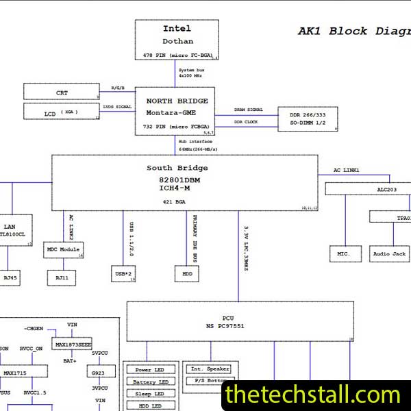
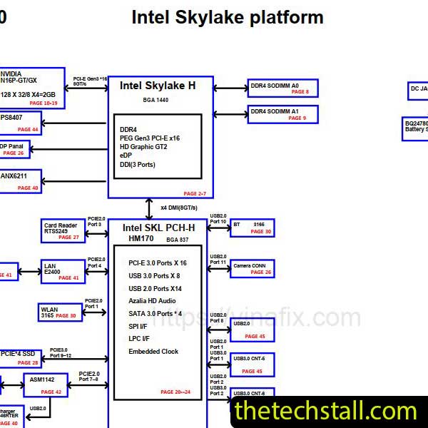
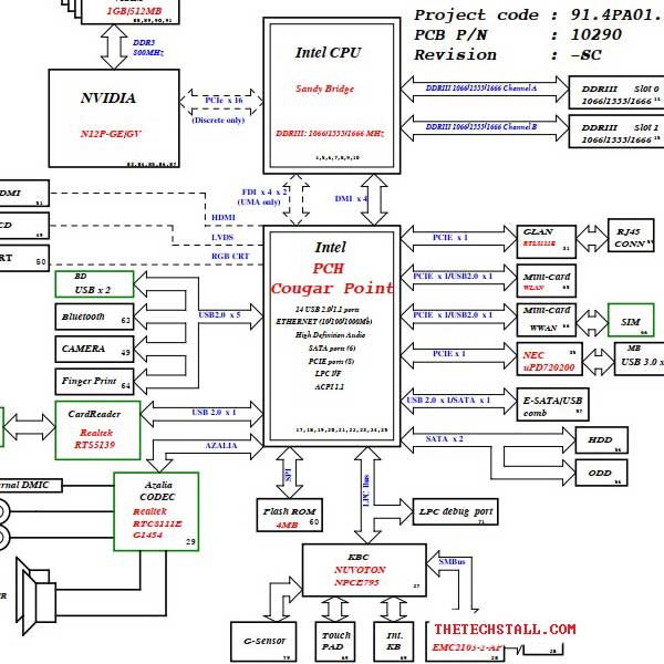
The 10290-2 Schematic Diagram serves as a roadmap for the Lenovo B570 motherboard. It lays out every electronic pathway, circuit, and component connection in a structured and easy-to-understand format. Without a proper schematic, diagnosing faults such as no power, no display, or charging issues becomes a game of trial and error. However, with this schematic in hand, technicians can pinpoint the exact location of the fault and determine whether a component needs replacement or if a circuit line is broken.
This diagram saves countless hours of guesswork, helping professionals and hobbyists alike understand how signals flow through the motherboard. Whether you’re dealing with voltage rail issues or short circuits around the CPU or GPU sections, the 10290-2 Schematic Diagram provides all the detailed information you need to repair efficiently and confidently.
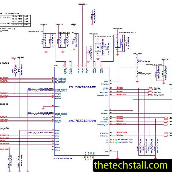
One of the biggest challenges in motherboard repair is tracing faults at the chip level. Motherboards like the Lenovo B570 feature densely packed integrated circuits that make manual tracing extremely difficult. The 10290-2 Schematic Diagram bridges this gap by offering a clear and accurate representation of the board’s architecture.
Here are some ways technicians benefit from it:
While the 10290-2 Schematic Diagram is a must-have document for deep-level troubleshooting, combining it with other repair resources enhances accuracy and efficiency. Here are a few additional tools and resources that pair well with this schematic:
Whether you are an experienced motherboard technician or just starting out in laptop repair, having the right documentation can dramatically improve your accuracy and success rate. The 10290-2 Schematic Diagram not only boosts confidence but also helps you build a systematic approach to diagnosing and fixing faults.
It reduces repair risks, saves time, and ensures that you’re working based on verified electrical information instead of assumptions. Moreover, when combined with a good multimeter, power supply, and hot air rework station, it becomes part of a complete chip-level repair setup for the Lenovo B570 motherboard.
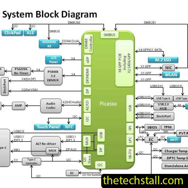
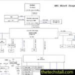
When working with the 10290-2 Schematic Diagram, always start with the “Power Block Diagram” page. This high-level view shows how voltage is distributed across the board. If the primary 19V rail (B+) is missing, there is no point in checking the CPU VCore.
Secondly, always use a DC Power Supply with an ammeter. By observing the current draw (amps), you can correlate the board’s behavior with the stages of the power sequence outlined in the schematic.

For tips on chip-level repair of laptop and desktop motherboards, visit our YouTube channel Repair Assistant and subscribe to our Facebook page repairassiastantbd for repair resource updates.
If you’re working on the Lenovo B570 and need reliable repair guidance, having the 10290-2 Schematic Diagram by your side will make all the difference.