For laptop motherboard technicians, accurate diagnosis is everything. When dealing with chip-level faults on laptops like the HP Envy x360-A, guesswork can waste hours and damage components. This is where the Y61 DA0Y61MB6E0 Schematic Diagram becomes an essential repair companion. Designed for precision troubleshooting, this schematic diagram helps technicians understand the motherboard’s design, signal flow, and power architecture—making even complex repairs more manageable.
The HP Envy x360-A motherboard is built with tightly packed ICs, multilayer PCB traces, and shared power rails. Common issues such as:
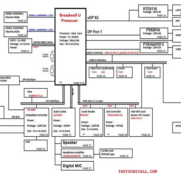
Cannot be resolved efficiently without a proper reference. The Y61 DA0Y61MB6E0 Schematic Diagram provides a complete electrical map of the motherboard. It shows how voltage regulators, MOSFETs, coils, BIOS, EC, and chipset are interconnected. With this information, technicians can move directly from symptom to root cause instead of randomly replacing parts.
Power issues are among the most common HP Envy x360-A faults. The schematic clearly outlines:
Using the Y61 DA0Y61MB6E0 Schematic Diagram, a technician can verify whether voltages appear in the correct order and quickly identify where the sequence breaks.
Instead of tracing PCB tracks visually, technicians can use the schematic to:
This is especially useful when diagnosing no-display, no-boot, or shutdown-after-few-seconds problems.
The schematic lists reference designators for:
This allows fast identification of faulty components and helps avoid replacing the wrong part—saving time and cost.
Using the Y61 DA0Y61MB6E0 Schematic Diagram, technicians can confidently handle:
The schematic acts as a logical roadmap, reducing trial-and-error troubleshooting.
To maximize repair success, experienced technicians often combine the schematic with additional resources:
A boardview file complements the schematic by showing the physical placement of components on the PCB. When used together, technicians can quickly locate components shown in the Y61 DA0Y61MB6E0 Schematic Diagram.
The schematic tells you where to measure; these tools tell you what is happening.
The service manual helps with:
While it doesn’t replace the schematic, it works well alongside it.
BIOS corruption is common. Using a verified BIOS file together with the schematic ensures correct flashing points and voltage checks.
When a short circuit is present, a thermal camera can quickly identify the heating component referenced in the schematic.
To make your repair work faster and more accurate, you can download the Y61 DA0Y61MB6E0 Schematic Diagram using the link provided below:
Download “HP Envy x360-A Series Quanta Y61 DA0Y61MB6E0 Rev 1A Schematic” HP-Envy-x360-A-Series-Quanta-Y61-DA0Y61MB6E0-Rev-1A-Schematics.zip – Downloaded 1141 times – 1.91 MBProfessional motherboard repair is about accuracy, not speed alone. The Y61 DA0Y61MB6E0 Schematic Diagram:
Whether you’re handling daily repairs or complex chip-level faults, this schematic diagram turns the HP Envy x360-A motherboard into a readable, understandable system rather than a mystery.

For tips on chip-level repair of laptop and desktop motherboards, visit our YouTube channel Repair Assistant and subscribe to our Facebook page repairassiastantbd for repair resource updates.