How a skilled technician harnesses the power of the DA0ZRWMB6G0 schematic diagram to revive Acer Aspire V3-575 laptop motherboards.
In the realm of laptop repair, few tasks are as daunting as reviving a motherboard. When it comes to the Acer Aspire V3-575 series, technicians often find themselves faced with intricate circuitry and elusive faults. However, armed with the powerful tool that is the DA0ZRWMB6G0 schematic diagram, skilled technicians can navigate this labyrinth of circuits and breathe new life into seemingly lifeless motherboards.
Understanding the Acer Aspire V3-575:
The Acer Aspire V3-575 laptop is a marvel of modern engineering, boasting powerful hardware and sleek design. However, like all electronic devices, it is not immune to malfunctions. Motherboard issues can arise due to a variety of reasons, including power surges, component failures, and environmental factors. When faced with a non-functional Acer Aspire V3-575 motherboard, a skilled technician must embark on a journey to diagnose and repair the underlying faults.
The Power of the DA0ZRWMB6G0 Schematic Diagram:
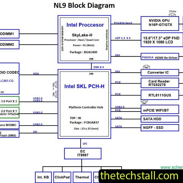
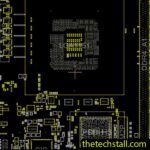
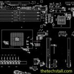
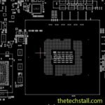
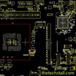
At the heart of every successful motherboard repair lies the schematic diagram. In the case of the Acer Aspire V3-575, the DA0ZRWMB6G0 schematic diagram serves as a roadmap, guiding technicians through the intricate web of circuits and components. This invaluable resource provides detailed insights into the inner workings of the motherboard, allowing technicians to identify faulty components, trace signal paths, and understand the interactions between different parts of the circuit.
Diagnosis and Troubleshooting:
With the DA0ZRWMB6G0 schematic diagram in hand, the technician begins the diagnostic process by carefully inspecting the motherboard for visible signs of damage, such as burnt components or corroded traces. Next, using specialized tools such as multimeters and oscilloscopes, they systematically test various components and measure voltage levels to pinpoint the root cause of the issue. The schematic diagram serves as a reference throughout this process, helping the technician interpret their findings and make informed decisions about the necessary repairs.
Repair and Restoration:
Once the faulty components have been identified, the technician sets out to repair or replace them, following the guidelines laid out in the schematic diagram. This may involve desoldering and replacing damaged ICs, capacitors, or resistors, or repairing broken traces using conductive ink or wire. With each component restored to working order, the motherboard gradually comes back to life, its circuits pulsating with renewed energy.
Download “Acer Aspire V3-575 V3-575G ZRW DA0ZRWMB6G0 Schematic”
Acer-Aspire-V3-575-V3-575G-ZRW-DA0ZRWMB6G0.zip – Downloaded 185 times – 1.79 MB
Reviving a Acer Aspire V3-575 laptop motherboard is no small feat, but with the aid of the DA0ZRWMB6G0 schematic diagram, skilled technicians can overcome even the most challenging of obstacles. By harnessing the power of this invaluable resource, they unravel the mysteries of circuitry, breathe life into dead motherboards, and restore hope to those whose devices have faltered. In the ever-evolving landscape of technology, the art of motherboard repair remains a testament to the ingenuity and expertise of those who dare to venture into its depths.
Level Up Your Tech Skills: Dive into Laptop Motherboard Chip-Level Repair!