In the world of electronics, laptops have become an indispensable part of our lives. However, like all electronic devices, they are prone to occasional malfunctions and failures. When your Acer Aspire 5542 laptop encounters such issues, the process of diagnosing and repairing it might seem daunting. Thankfully, with the JV50-TR 8VRAM Rev-1 schematic diagram, repairing your laptop becomes a breeze, saving both time and money.
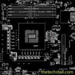
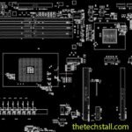
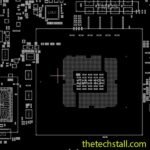
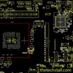
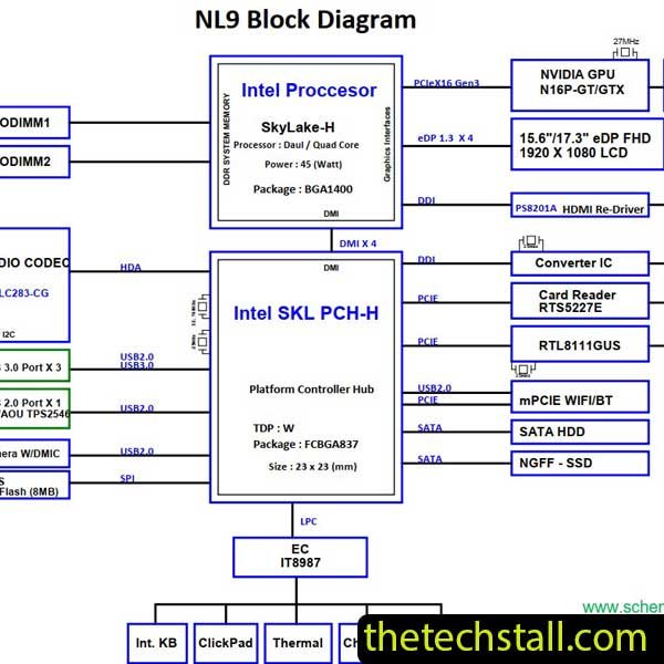
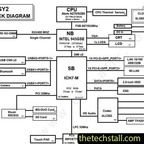
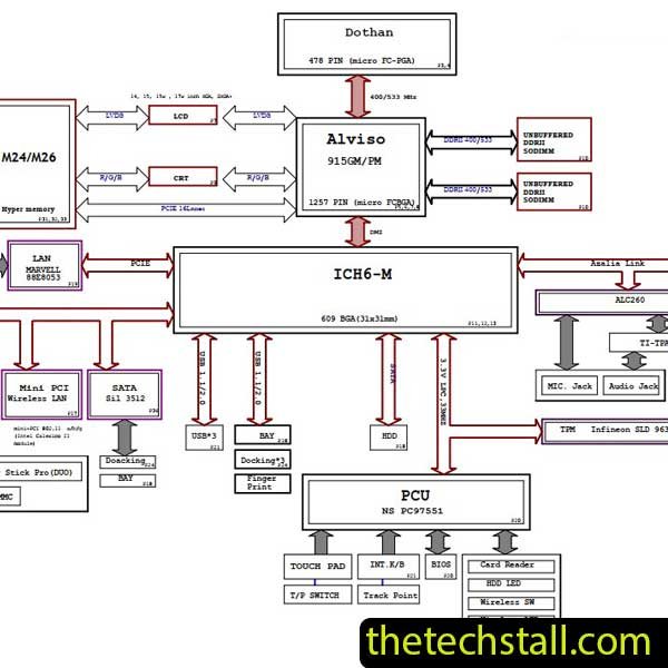
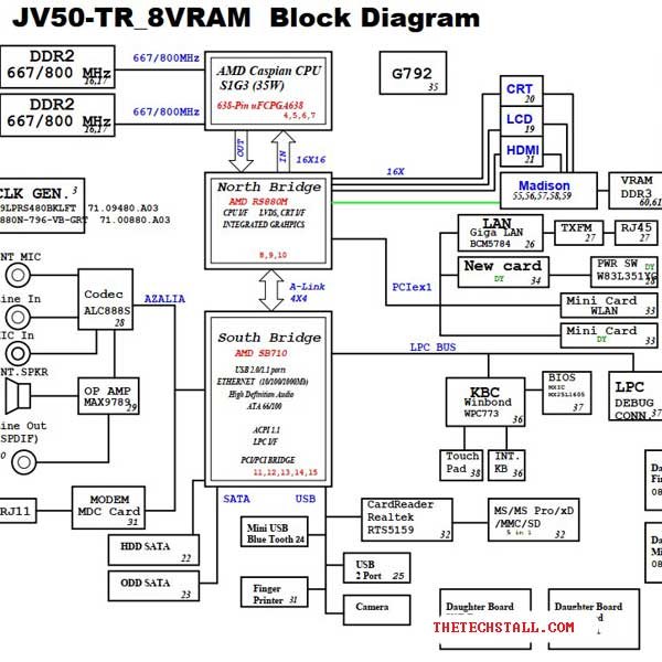
The JV50-TR 8VRAM Rev-1 schematic diagram is a graphical representation of the circuitry and connections within the laptop’s motherboard. It offers a detailed view of the components, showing their interconnections and signal paths. This valuable document is crucial for anyone involved in laptop repairs, as it serves as a guide to troubleshoot and identify faulty components accurately.
Welcome to the ultimate collection of laptop BIOS BIN files available for free download. In this comprehensive article, we will provide you with a vast selection of BIOS BIN files for various laptop models. Whether you’re an IT professional, a computer enthusiast, or someone looking to repair or upgrade your laptop, this collection will be an invaluable resource for you. Our goal is to provide you with the experience, expertise, authority, and trust necessary to confidently navigate the world of laptop BIOS files.
One of the primary advantages of using the JV50-TR 8VRAM Rev-1 schematic diagram is that it significantly reduces the time taken to identify and resolve issues. Without the schematic diagram, technicians might spend hours trying to trace faults manually. Additionally, by avoiding trial-and-error, you can save on repair costs, as you’ll be able to replace only the defective components, avoiding unnecessary part replacements.
Here is a step-by-step guide to efficiently repair your Acer Aspire 5542 laptop using the JV50-TR 8VRAM Rev-1 schematic diagram:
Before diving into the repair process, identify the laptop’s common issues and symptoms. These may include power failures, no display, overheating, or malfunctioning ports.
Refer to the schematic diagram to understand the laptop’s circuitry and signal flow. Identify the relevant sections corresponding to the detected issues.
Ensure you have all the necessary tools for the repair, including a soldering iron, desoldering pump, multimeter, and anti-static wrist strap.
Before starting the repair, take adequate safety precautions. Disconnect the laptop from the power source and discharge any static electricity from your body.
Use the schematic diagram to trace the signal paths and locate the faulty components. Perform tests using a multimeter to confirm their malfunction.
Carefully desolder the defective components and replace them with new ones. Follow best practices for soldering to ensure proper connections.
After the replacements, reassemble the laptop and test its functionality. Check all repaired sections to ensure that the issues have been resolved.
To carry out the laptop repair successfully, you’ll require the following tools and equipment:
we will show you how to download the BoardView file step-by-step, ensuring you have the correct version for your laptop model. We will cover the installation process and discuss the tools necessary to open and interpret the BoardView file.
To effectively troubleshoot laptop issues using the schematic diagram:
Issue: The laptop shows no signs of power, and the screen remains blank when attempting to turn it on.
Diagnosis: After consulting the JV50-TR 8VRAM Rev-1 schematic diagram, it is identified that there is a failure in the power circuit.
Repair: Upon further examination, a faulty capacitor in the power section is discovered. It is replaced with a new one, and the laptop powers on successfully.
Issue: The laptop’s display works intermittently, but there is no output on an external monitor when connected.
Diagnosis: The schematic diagram reveals a possible issue with the VGA port circuitry.
Repair: Upon inspection, a broken trace on the VGA connector is detected. Soldering the trace back together restores the video output to the external monitor.
Issue: All the USB ports on the laptop have stopped working.
Diagnosis: The schematic diagram helps identify that the USB controller chip is likely faulty.
Repair: After replacing the USB controller chip with a new one, the USB ports regain their functionality, allowing seamless connectivity with external devices.
Obtaining the JV50-TR 8VRAM Rev-1 schematic diagram is relatively easy. However, it’s crucial to ensure the authenticity and reliability of the source. Always verify that the diagram corresponds to the specific motherboard revision to avoid confusion during repairs. The file downloaded from here can be opened through Adobe Acrobat Reader or Foxit PDF READER software.
Download “Acer Aspire 5542 JV50-TR 8VRAM 48.4FN02.001 Rev-1 schematic”
Acer-Aspire-5542-JV50-TR-8VRAM-48.4FN02.001-Rev-1-schematic.zip – Downloaded 54 times – 1.25 MB
The JV50-TR 8VRAM Rev-1 schematic diagram proves to be an indispensable resource for repairing the Acer Aspire 5542 laptop efficiently and cost-effectively. By utilizing the detailed insights provided by the diagram, technicians can diagnose issues accurately and implement targeted repairs. This not only saves time but also reduces unnecessary expenses in replacing functional components. With the right tools, precautions, and troubleshooting techniques, repairing laptops becomes a more manageable task, and users can enjoy a fully functional device once again.
Share with friends
thetechstall.com would like to share with you all the resources you need to repair desktop and laptop motherboards for free.
Developed By: Ibrahim Hossen